www.wimb.net - Numerical Control History


TCI - Tape Controlled Indexer
Around 1965 the SLO-SYN series of numerical controls was started with the TCI. These units had a 10 character / second mechanical tape reader made by Tally. The TCI was only for point to point movements; is was really a construction of two indexers built together with a tape reader. The programming was in a special format. When a machine function has to be called, the move distance had to be extended with leading zero's an additional number for the machine function.

Around 1970 there came a new series of numerical controls. Made out of two basic models, these SLO-SYN N/C consoles are offered to permit the control capabilities to be matched to the requirements of the specific application. The model illustrates the two series and identifies the type of operations each is intended for. Detailed descriptions of the consoles follow. :
- NCIR24 - Point-to-Point Positioning
- NCCR25 - Continuous Path Contouring Control

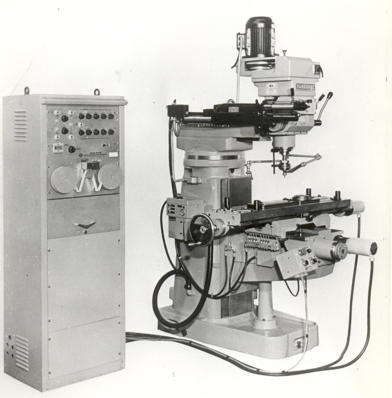
SLO-SYN NCIR24
SLO-SYN Numerical Tape Controls are two- or three-axis positioning systems for controlling point-to-point positioning or straight-line milling parallel to either axis or at a 45º angle. They are of modular construction and make extensive use of plug-in solid-state circuits which are easily replaced in case of a malfunction. EIA coding is standard, but ASCII codes are available as an option. All that is required is to plug-in the ASCII decoder board in place of the EIA decoder board supplied with the unit.
SLO-SYN Numerical Tape Controls have been designed so that they can be retrofitted easily to almost any machine. Motor coupling kits have been developed for a number of machines to further simplify the retrofitting operation.
Features
- Manual Data Input Plus Jog Control
- Mirror Image
- 3 Unassigned Miscellaneous Functions on Two-axis units; 2 on Three-axis units
- Backlash Take-Up Circuit-Can be Turned Off For Milling
- Milling Feed Rates From 0.75 to 18 Inches Per Minute
- Hi Feed Rates From 30 to 60 Inches Per Minute
- Tape Actuated Rapid Traverse When Milling
- Manual Data Input
Positioning and jogging of the machine table can be controlled from dials on the N/C console. The ability to precisely control positioning movements without tape is useful for performing extra operations not included on the tape or for setting up.
- Mirror Image
- When the mirror image mode is selected for the x or the y axis, a II table motions for that axis' wi II be in the opposite direction from that called for on tape. By selecting the mirror image mode for the appropriate axis, both left- and right-hand parts can be made from a single tape. With both axes in the mirror image mode, the program will be identical to that on tape, but in the opposite quadrant.
- Miscellaneous Functions
- Two-axis systems have three unassigned miscellaneous functions and three-axis systems have two. These functions can be used to control actions such as multiple spindle selection and coolant flow. In milling applications the functions can be used to operate a power spindle drive to feed and retract the tool.
- Backlash Take-Up Circuit
- The backlash take-up circuit compensates for play in lead screws by always making the final table approach to a position from the same direction, regardless of the previous table position. When traveling in the plus direction, the table will proceed directly to the final position. If travel is in the minus direction, the table will travel beyond the final position, and then return to it in the plus direction.
- Milling Feed Rates
- Milling Feed Rates with a 5pitch lead screw are 0.75, 1.5, 3, 6, 10 and 18 inches per minute. Rates with a 10-pitch lead screw are 0.375, 0.75, 1.5, 3, 5 and 9 inches per minute. Speed of the two axes is synchronized at all but the highest feed rate, allowing true 45-degree table motions to be performed. A dial on the control panel selects the feed rate.
- Rapid Traverse
- When operating at a table speed of 18 inches per minute or less, the speed can be changed to the Hi rate by inserting a code in the tape program. The control unit will position the table at the Hi feed rate and then revert to the lower feed rate.

SLO-SYN Continuous Path Contouring Control Type NCC.
The threefold increase in positioning speed and new feed rate control from tape are strong competive features of SLO-SYN Continuous Path Contouring Controls. These N/C units are used for machining parts involving arcs, angles and complex shapes as well as straight cuts.
NCCR25 - Continuous Path Contouring Control
Point-to-point controllers such as SLO-SYN Numerical Tape Controls are extremely worthwhile controls that have brought the benefits of N/C to a wide range of metalworking machines. However, a need still existed for a realistically priced controller that could perform contouring. SLO-SYN Continuous Path Contouring Controls met that need.
The controls have linear and circular interpolation; essentially, a small computer circuit that permits the tool to be moved along slopes, arcs and circles with a minimum of program input. Other features of the controls are:
Features
- Full Linear and Circular Interpolation in the Lo Feed Range
- Lo Speed Range Adjustable from 0 to 18 Inches Per Minute
- Accept Either EIA or ASCII Codes
- Buffer Storage
- 6 Unassigned Auxiliary Functions on Two-Axis Units; 5 on Three-Axis Units
- Enclosed Photoelectric Tape Reader
- Manual Data Input and Jog Control
- Mirror Image
- Sequence Number Display
- Positioning done with SLO-SYN Precision Stepping Motors
- Tape Actuated Rapid Traverse When Milling
- Tool Inhibit Command
- Eye-Level Control Panel
- Easily Retrofitted to Most Machines
- Linear Interpolation
- The control automatically adjusts the commands to each drive motor so that the table will travel from one position to the next in a straight line when operating in the Lo feed range. Therefore, any angle can be produced by programming the x and y-axis increments to the next point.
- Circular Interpolation
- Programming of circular cuts in any quadrant or less can be done in a single data block by describing the x and y axis increments and the location of the center of the arc. As a result, tape program length is reduced and the need for time consuming calculations is eliminated.
- Buffer Storage
- The incorporation of buffer storage allows the control to read and store a block of information while previous information is being acted upon. Buffer storage allows tool movements to be made in one continuous motion with no pause between blocks of information.
- Constant Tool Speed
- The speed at which the tool moves through the work remains at the preselected rate, even when a slope or an arc is being performed.
- Manual Data Input
- Positioning and jogging can be controlled from the front panel when necessary. Manual data input allows the operator to set up the equipment as well as position without tape. Linear interpolation is in effect when positioning from the manual input controls in the Lo feed rate setting.
- Table Speeds
- The Speed switch allows selection of a Hi or Lo range. Table speeds in the Hi range are from 30 to 60 inches/minute and speeds in the Lo range are from 0-18 inches/minute based on a 5 pitch lead screw. In the Lo range, speed can be adjusted down to zero without losing information. Control of the Lo speed can be switched by tape from the normal Lo speed control to a second control that can also be set at any speed from 0 to 18 inches per minute. Another tape command switches the N/C from Lo to Hi speed, thus permitting selection of any of three speeds from tape.
- Mirror Image
- Symmetrical right- and left-hand parts can be produced from the same tape by using the mirror image mode. In effect all direction signs are reversed from those called out on the tape when the mirror image mode is selected.
Applications
In addition to machine tools and metalworking equipment SLO-SYN Continuous Path Controls can be applied to automatic drafting, wiring or photo engraving machines, optical comparators, chemical milling equipment, map plotters, component inserters, welders, assemblers, parts or material dispensers, woodworking equipment, textile cutting and shaping machines and virtually any other apparatus requiring two- or three axis positioning capabilities.
Their programming simplicity, ease of operation and versatility add increased capabilities without the complex feedback systems required with closed loop systems. A wide choice of torque ratings allows selection of the optimum power range for any application from small positioning tables up to large machining centers.


Updated 2007 Oct. 09