www.wimb.net - iButton Adapter
iButton Adapter

IButton Links
iButton Adapter
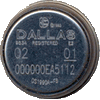
While I was searching in one of my junk boxes, I found an old battery; at least it looked like a battery. After a close examination it turned out to be an "iButton" type number: DS1990A-F4, made by Dallas/Maxim.
After reading the PDF manuals on Internet, I decided to make a small interface with a Delphi program to see if the iButton was still readable. Well, it works!
Delphi Program
![]() For the software I've made a small Delphi program that with the 1-Wire protocol via this adapter can read the serial number of the iButton.
For the software I've made a small Delphi program that with the 1-Wire protocol via this adapter can read the serial number of the iButton.

The iButton
An iButtonTM is a chip housed in a stainless steel enclosure. The electrical interface is reduced to the absolute minimum, i.e., a single data line plus a ground reference. The energy needed for operation is "stolen" from the data line ("parasitic power"). The logical function of the DS1990A is a simple serial number. This globally unique registration number is common to all iButtons.
For read operations all devices are satisfied with a 5kOhm pull-up resistor to supply energy and to terminate the 1-Wire bus.
Adapter Construction

To adapt the RS232 signal levels to the 1-Wire bus you need a small adapter. See the images below. It's built on a small part of a prototyping board (25 x 18 mm) that is soldered on the connector pins of the 9 pole connector. Most parts are SMD, but there are also a few discrete resistors.

The board has also a LED that is controlled by Pin 4 and Pin 7 of the RS232 connector. This LED has no use for the 1-Wire adapter, but you can prove that the adapter is controlled by the program. Please note that this LED was added later and is not drawn on the diagram below.
Power
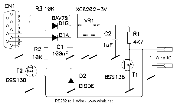
The power comes from the RS232 connecter via DTR (Pin 4) and / or CTS (Pin 7). Depending of the computer, this tension may vary from 5 to 12 volt. To be sure to have a constant voltage, a small regulator (VR1) is used. This on has an output of 3V, but 5V would also be good.
TX
The TX signal goes via R2 to the gate of T1. The diode D2 cuts away the -12V. Without transmission the TX output is -12V and T1 does nothing, the output to the 1-Wire bus is 3V, coming via R1. When TX goes positive, +5V to +12V, T1 starts to conduct and the tension on the 1-Wire bus drops to 0V.
RX
Since the 1-Wire bus has only one wire (and ground), the input is connected to the output. So, the 0 to 3 Volt pulses made by T1 are direct seen by T2. The output from T2 is via a pull-up resistor (R3) connected to the RS232 RX input. Every pulse send by TX goes back to RX, like an external echo.
Updated 2007 Oct. 09


