www.wimb.net - Digital Nixie Clock
Digital Clock with Nixie Tubes

Around 1971 we got the first series of TTL IC's from Texas Instruments. But what to do with these very nice looking black things? Since I was always interested in clocks, I decided to make a digital clock.
Start
First the components were selected and the schematic diagram was made. At that time there was a printed circuit for a digital counter board available. This board was not so very expensive, so it was bought and slightly modified for the clock.
The print was made for a five digit counter with Nixie Tubes and therefore the seconds were left out. It is much easier to leave a digit away then to add an extra one.
Operation
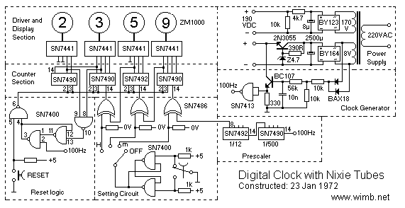
The schematic diagram shown at the bottom of this page, can be separated in different logic sections. They are described below.
Power Supply
The power transformer has two secondary windings; one for the logic voltage and one for the 190 volt to drive the Nixie tubes. The current taken from the 190 volt supply is very low; therefore the capacitor can be small. The logic current is a bit more with all these current consuming TTL IC's; a 2N3055 and a zener diode are used to make the 5 volt.
Clock Pulse Generator
Two signal diodes are picking up the 8 volt AC and makes a nice 100 Hz signal from it. This signal goes via a HF noise filter to a transistor BC107 and then to the input of a SN7413 Schmitt-trigger. The output from there is a nice and clean 100 Hz pulse. The main frequency is very suitable to run a clock on; it is really stable and also corrected on the long term to have the exact number of counts, at least in The Netherlands.
Prescaler
Then the 100 Hz goes to a divide by 500 counter, made out of three SN7490, 10 x 10 x 5 and this is followed by a SN7492 and there divided by 12. The output frequency is 0.01667 Hz, one pulse per minute.
Counters and Display
This "one per minute pulse" goes to the minute counter, a divide by ten SN7490. The minutes are followed by the ten minutes. That is done with a SN7492, a "divide by 12" counter. Since this one does not go higher then 5, only the three lowest outputs are used.
The hours are made with a similar construction, except that there are now two SN7490. Form the ten hours counter only two outputs are used, it counts from 0, 1 to 2 and then back to 0.
The outputs of each counter are going to an SN7441, the Nixie driver chip. Only the really used outputs are connected. This gave me the opportunity to use some second hand chips with a few defective outputs. The new and good chips were very expensive at that time.
24 Hours
The clock counts like a normal European clock i.e. from zero to 24 hours. On the output of the hour counters is a NAND gate connected, one input to the 4 (hours) and the other one to the 20. When the clock goes to 2400 then the 24 makes the pin 8 of the NAND gate low. The pin 13 goes low and that make pin 1 high. Now, when the 100 Hz pulse goes high, pin 3 becomes low and that makes pin 6 high. This is connected to the reset of all counters, so they restart from zero. And that's what I want. In addition there is a switch to set the clock on zero.
Setting Circuit
The clock has a small circuit to set it at the correct time, for example when you have to change from summer to winter time. It is made of three XOR gates and a flip-flop. With a selection switch, the digit to be set can be selected, then a push on the pushbutton increments the counter. The flip-flop is really necessary; any contact bouncing may forward a counter with tens of counts. TTL is very fast. There is also a reset button, to put the time on 00.00 hours.
Housing

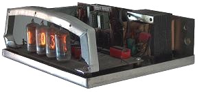
When the clock was up and running for the first time it was an open frame construction, as shown on the image at the top of this page. Then the problem was to find a nice housing for the clock. Since a digital clock was a very futuristic device in 1972, I designed and made a construction with a futuristic "flying sourcer" look. The housing is sliding over the clock and fixed on the mechanical friction. The clock itself is with on large screw fixed on the wall.
DataSheets
Here are some of the datasheets for online read or download:

SN7413

SN7400

SN7486

SN7490

SN7441

ZM1000
Schematic Diagram
This is the schematic diagram of the Digital Nixie Clock. Please note that not all details are shown.

Updated 2007 Oct. 09


